Electrical Connections
- Trailer Connectors keyboard_arrow_right
- Air Products & Electrical Assemblies keyboard_arrow_right
- Terminals & Connectors keyboard_arrow_right
- Wire & Cable keyboard_arrow_right
- Support & Protective keyboard_arrow_right
- Switches & Electrical Assemblies keyboard_arrow_right
- Battery Connectors & Cable keyboard_arrow_right
- Kits & Tools keyboard_arrow_right
Company
- Company Profile keyboard_arrow_right
- Careers keyboard_arrow_right
- Case Studies keyboard_arrow_right
- Contact Us keyboard_arrow_right
- Media Center keyboard_arrow_right
- Grote News keyboard_arrow_right
- Trade Shows & Events keyboard_arrow_right
- Quality keyboard_arrow_right
- Star Safety Technologies by Grote keyboard_arrow_right
Tech Support & Information
Customer Information
Knowledge Base
Were to find a install instruction for 78473 light bar? Or trouble shooting. Unit just blinks on the pad does not light up lights on bar.
Grote's Answer
The most up-to-date installation instructions can be found on the product page, under related information. For help with troubleshooting, please reach out to our technical support team by clicking on our Live Chat at the bottom right of your screen, or request a call back by submitting your contact information under the “Technical Questions / Support” option on our Contact Us Form.
———-
Installation Instructions – Grote 78473 LED Safety Director Directional Light(as of 11/2018 | 920-0423-00 Rev. A)
This LED directional signal is a high-intensity directional warning system designed to direct traffic approaching from the rear of a stationary vehicle. The unit can be mounted either flush to the vehicle or with the provided mounting brackets and is suitable for interior or exterior use. It also features an easy to use, soft-touch controller that provides fingertip control of the eight built-in fl ash patterns and mimics the selected pattern in real time.
Unpacking: Carefully remove the unit and place it on a flat surface. Examine the unit for transit damage, etc. If the vehicle has an electrical system other than 12 or 24 Volts DC negative ground, contact your local representative or call the manufacturer for instructions.
Installation & Mounting: The director was designed with a flexible mounting system which allows it to be mounted almost anywhere. For questions concerning a specific application call customer service. Prior to mounting, consideration should be given to cable location. The cable should exit the end cap on the left side of the director as you face the front of the light bar. Reversed mounting will result in all of the flash patterns being reversed. The mounting location should be chosen such that there is maximum visibility to the oncoming traffic.
Horizontal Surface Mounting:
- Place the light bar on a flat surface, and install the mounting brackets on the rear of the bar with the supplied hardware as shown. Leave the hardware loose, so that the brackets are movable.
- Place the light bar in the selected location, and mark the hole locations. Adjust the mounting brackets as necessary.
- Drill holes for ¼” mounting hardware (user supplied).
- Install the light bar with the hardware and secure.
Vertical Surface Mounting:
- Determine the proper height for the light bar, to ensure good visibility.
- Drill the holes for the ¼” carriage bolts, using the mounting bracket as a template for spacing. Make sure the holes are spaced evenly from the ends of the light bar, and at the same height.
- Mount the light bar with the supplied hardware, and secure.
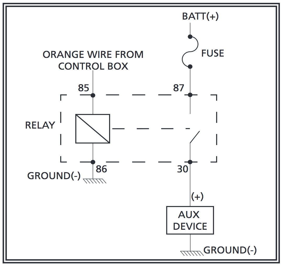
Wiring: Wire the director into the vehicle’s 12 or 24 Volt system. Provide a 5A fuse near the power take off. Use 16AWG wire or larger for the Red and Black wire connections. If the Auxiliary Output is not used, cap the orange wire from the Control Box. Route the light bar cable from the Stick to the Control Box and plug them together.
Wiring for Auxiliary Output: An auxiliary device, such as a beacon, light bar, work lamp, etc. can be controlled by the “ALT” button of the control box. This device should not exceed 20A. Wire the relay that is provided into the system, making sure that the auxiliary device is properly wired and fused according to the manufacturer’s requirements.
Notes:
- Larger wires and tight connections will provide longer service life for components. For high current wires it is highly recommended that terminal blocks or slidered connections be used with shrink tubing to protect the connections. Do not use insulation displacement connectors (e.g., 3M Scotchlock type connectors). Route wiring using grommets and sealant when passing through compartment walls. Minimize the number of splices to reduce voltage drop.
- High ambient temperatures (e.g., under-hood) will significantly reduce the current carrying capacity of wires, fuses, and circuit breakers. All wiring should conform to the minimum wire size and other recommendations of the manufacturer and be protected from moving parts and hot surfaces. Looms, grommets, cable ties, and similar installation hardware should be used to anchor and protect all wiring.
- Fuses or circuit breakers should be located as close to the power takeoff points as possible and properly sized to protect the wiring and devices.
- Particular attention should be paid to the location and method of making electrical connections and splices to protect these points from corrosion and loss of conductivity.
- Ground termination should only be made to substantial chassis components, preferably, directly to the vehicle battery.
- Circuit breakers are very sensitive to high temperatures and will “false trip” when mounted in hot environments or operated close to their capacity.
CAUTION: Disconnect the battery before wiring up the Directional Signal to prevent accidental shorting, arcing, and /or electrical shock.
CAUTION: This system must be connected to a separate, fused power point. Do not wire in parallel with any other accessory.
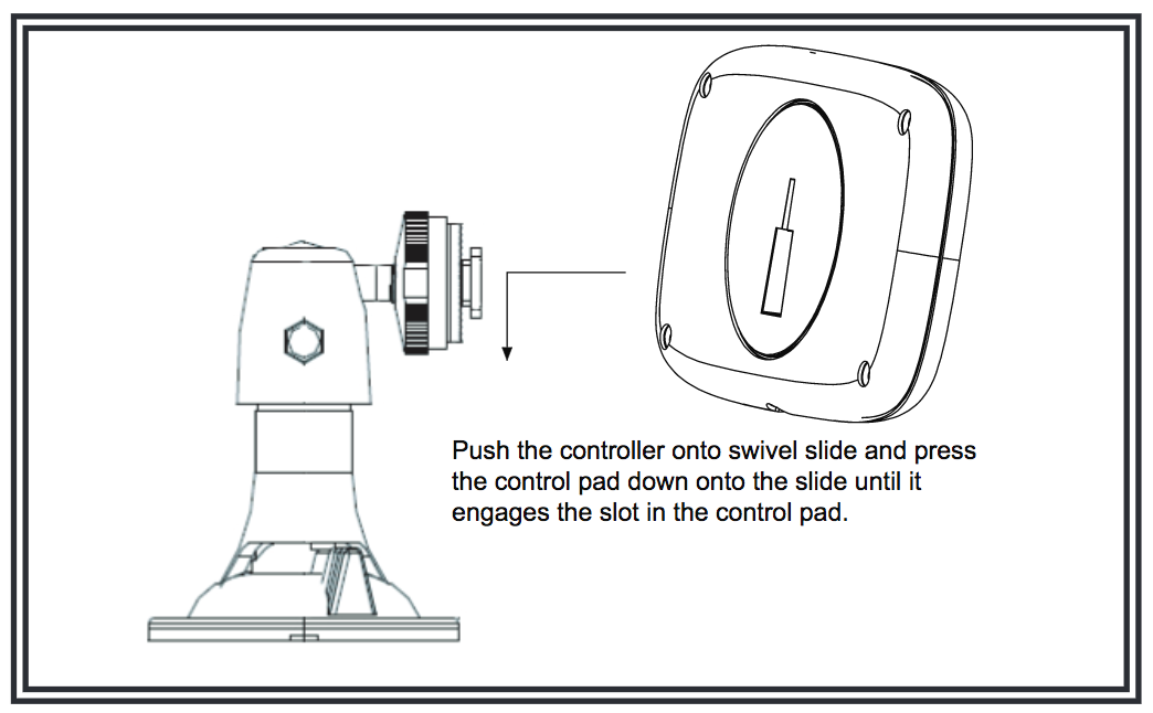
Control Pad Mounting: To mount the control pad with Velcro, separate the two circular halves, remove the backing and adhere one piece on the vehicle dashboard and adhere the other to the back of the controller. To mount the control pad using the swivel mount, first mount the swivel unit to the dashboard with either the supplied screws (note, the suction cup will not work after drilling screws through the swivel base) or by turning the lever at the base of the swivel unit to engage the suction cup. Push the controller onto swivel slide and press the control pad down onto the slide until it engages the slot in the control pad(see Figure 5). (You may need to turn the controller clockwise once engaged with the slide to tighten it.) Turn the dial on the swivel head to tighten it against the back of the control pad. Finally, loosen the hand screw on the swivel neck to adjust the angle of the control pad. Hold the pad in the desired position while tightening the hand screw on the swivel neck.
Operation: Press the left power button to turn the unit on/off. The left arrow button alternates between left arrow and left continuous arrow fl ash modes. The mode button alternates between center out, center out solid, wig wag, alternating, and alternating quad fl ash modes. The right arrow button alternates between right arrow and right continuous arrow fl ash modes. The ALT button is for the auxiliary control on/off.
Maintenance: The director requires little routine maintenance. Occasional cleaning of the lenses is all that is required to maintain maximum light output. Use plain water and a soft cloth, or lens polish and a very soft paper towel or facial tissue. Since plastic scratches easily, cleaning is recommended only when necessary. Do not use solvents as they may damage the polycarbonate lens material.
If a problem does develop, refer to the Troubleshooting Guide below:
| Symptom | Possible Cause |
|---|---|
| No functionality of Control Box or Stick | Main power fuse is blown, or poor connection |
| One or more segments of Stick do not light | Stick is defective |
| One Control Box LED blinks continuously | Poor connection between Control Box and Stick |
| Aux device will not turn on | Aux fuse is blown, or poor connection |
| Aux device will not turn off | Relay is shorted from excessive load current |
Flash Patterns:

WARNING!
Failure to install or use this product according to manufacturers recommendations may result in property damage, serious bodily/personal injury, and/or death to you and those you are seeking to protect!
Do not install and/or operate this safety product unless you have read and understand the safety information contained in this manual.
- 1. Proper installation combined with operator training in the use, care, and maintenance of emergency warning devices are essential to ensure the safety of emergency personnel and the public.
- 2. Emergency warning devices often require high electrical voltage and/or current Exercise caution when working with live electrical connections.
- 3. This product must be properly grounded. Inadequate grounding and/or shorting of electrical connections can cause high current arcing, which can cause personal injury and/or severe vehicle damage, including fire.
- 4. Proper placement and installation are vital to the performance of this warning device. Install this product so that output performance of the system is maximized and the controls are placed within convenient reach of the operator so that s/he can operate the system without losing eye contact with the roadway.
- 5. It is the responsibility of the vehicle operator to ensure daily that all features of this product work correctly. In use, the vehicle operator should ensure the projection of the warning signal is not blocked by vehicle components (i.e., open trunks or compartment doors), people, vehicles, or other obstructions.
- 6. The use of this or any other warning device does not ensure all drivers can or will observe or react to an emergency warning signal. Never take the right-of-way for granted. It is your responsibility to be sure you can proceed safely before entering an intersection, driving against traffic, responding at a high rate of speed, walking on or around traffic lanes.
- 7. This equipment is intended for use by authorized personnel only. The user is responsible for understanding and obeying all laws regarding warning signal devices. Therefore, the user should check all applicable city, state, and federal laws and regulations. The manufacturer assumes no liability for any loss resulting from the use of this warning device.
Not the answer you're looking for? Submit your question and we will get back to you with our answer.
Ask us a Question!
Can't find the answer that you we're looking for? Please fill out the following form and once answered, we will add it to our FAQ.
We will not publish your name or email address. Thank you!

