
When you have successfully completed this section, you will have mastered:
In some cases, the only solution to repairing a problem is to replace a wire. In that case, it’s important to follow the procedure outlined below.
Determine The Length Of The Run
Calculating the length of run requires a measurement referred to as the “most distant point.” Care must be taken to calculate the actual length. That means allowing for connections, providing slack to reach around obstacles and generally making sure that the length of run is not understated. For example, a rear trailer light mounted in the center might need to be fed from the side instead of down the center. That extra run could double the length of the wire.
With the length of run known, calculate the total amperage load by adding together the amperage draw for all of the devices that will require power on that circuit. With these two calculations complete, the correct wire size can be determined.
Calculate The Actual Length Of Each Wire Run
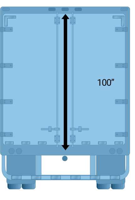
There may be 100” between the point where the wiring harness terminates (below the floor of the trailer) and the lights (above the door) that you wish to connect.
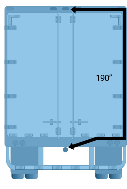
The wire must be routed over to the side of the trailer, up the wall, and back across the ceiling to the lights.The actual run is closer to 200”.
Using the “Wire Size” chart provided below, first find the load in amps in either the first or second column. Note that the first column shows the values for a 12-volt system. The second column shows the values for a 6-volt system.
Then find the length of run across the top of the chart. If you don’t find your exact length, always go to the next highest length. In other words, if your length of run is 61 feet, use the column labeled 70 feet. Read down that column until it intersects with the amp load line. The point at which they cross indicates the correct wire size for the job.
WIRE SIZE CHART |
|||||||||||
For A 12-Volt System |
For A 6-Volt System |
Length of Wire (Most Distant Light) |
|||||||||
10’ |
20’ |
30’ |
40’ |
50’ |
60’ |
70’ |
80’ |
90’ |
100’ |
||
Load in Amps |
Load in Amps |
Wire Gauge |
Wire Gauge |
Wire Gauge |
Wire Gauge |
Wire Gauge |
Wire Gauge |
Wire Gauge |
Wire Gauge |
Wire Gauge |
Wire Gauge |
1.0 |
0.5 |
18 |
18 |
18 |
18 |
18 |
18 |
18 |
18 |
18 |
18 |
1.5 |
0.75 |
18 |
18 |
18 |
18 |
18 |
18 |
18 |
18 |
18 |
18 |
2.0 |
1.0 |
18 |
18 |
18 |
18 |
18 |
18 |
18 |
16 |
16 |
16 |
3.0 |
1.5 |
18 |
18 |
18 |
18 |
18 |
16 |
16 |
16 |
14 |
14 |
4.0 |
2.0 |
18 |
18 |
18 |
16 |
16 |
16 |
14 |
14 |
14 |
12 |
5.0 |
2.5 |
18 |
18 |
18 |
16 |
14 |
14 |
14 |
12 |
12 |
12 |
6.0 |
3.0 |
18 |
18 |
16 |
16 |
14 |
14 |
12 |
12 |
12 |
12 |
7.0 |
3.5 |
18 |
18 |
16 |
14 |
14 |
12 |
12 |
12 |
12 |
10 |
8.0 |
4.0 |
18 |
16 |
16 |
14 |
12 |
12 |
12 |
10 |
10 |
10 |
10.0 |
5.0 |
18 |
16 |
14 |
12 |
12 |
12 |
10 |
10 |
10 |
10 |
11.0 |
5.5 |
18 |
16 |
14 |
12 |
12 |
10 |
10 |
10 |
10 |
8 |
12.0 |
6.0 |
18 |
16 |
14 |
12 |
12 |
10 |
10 |
10 |
8 |
8 |
15.0 |
7.5 |
18 |
14 |
12 |
12 |
10 |
10 |
10 |
8 |
8 |
8 |
18.0 |
9.0 |
16 |
14 |
12 |
10 |
10 |
8 |
8 |
8 |
8 |
8 |
20.0 |
10.0 |
16 |
16 |
12 |
12 |
10 |
10 |
8 |
8 |
8 |
8 |
Since heat has the effect of increasing resistance and diminishing the capacity of the wire, it makes sense to determine the possible effect that the operating temperature might have on the wire choice.
To do that, find the suggested wire size (from the prior exercise) on the left edge of the “Temperature Chart” provided. On that line, read across to the temperature column that reflects the operating environment. At that intersection, read the maximum allowable amp carrying capacity. Confirm that the maximum amp load indicated is greater than or equal to the load in the new circuit. If not, choose a heavier gauge wire and then check the temperature chart one more time.
TEMPERATURE CHART
Maximum Current Carrying Capacity (For 12 Volts at Listed Temperatures)
Cable Size |
120° F |
125° F |
150° F |
|---|---|---|---|
20 Gauge |
15 Amps |
13 Amps |
9 Amps |
18 Gauge |
18 Amps |
15 Amps |
11 Amps |
16 Gauge |
22 Amps |
19 Amps |
14 Amps |
14 Gauge |
27 Amps |
23 Amps |
17 Amps |
12 Gauge |
40 Amps |
32 Amps |
24 Amps |
10 Gauge |
50 Amps |
42 Amps |
31 Amps |
Note: Currents above those listed may increase the temperatures of the PVC above a safe design level of 180° F.
Truck Lighting Regulations
Although lighting is a major component of the safety equipment on any vehicle, nowhere is it more important than on trucks. There are some very specific regulations that apply to them, especially the number of lights and the placement.
The regulations that are encountered on a regular basis are contained in rules enforced by the National Highway Traffic Safety Administration (NHTSA). It’s a federal agency with jurisdiction over the entire country, and it should be noted that NHTSA regulations take priority over state or local regulations.
The Federal Motor Vehicle Safety Standard are the requirements provided by NHTSA for vehicle safety. FMVSS 108 is regulation that specifies the performance, numbers and location of lights on vehicles. The standard is referred to as FMVSS 108. The FMVSS 108 information chart (see pages 84 and 85) provides a concise explanation of the requirements and a way to become familiar with the basics of truck lighting. Let’s consider how this applies to trailer setup.
The chart is based upon a grid. The information reading left to right across describes the equipment, the mandatory quantities, and other requirements. Reading from top to bottom, the chart shows the requirements beginning with what is required for all trailers in the top section.
Additional requirements are triggered as a trailer’s size and weight increase. Those requirements are detailed in sections of the chart below the basic requirements toward the bottom of the chart. Keep in mind that the basic requirements are fixed and that larger and heavier means adding more equipment.
A closer look at a typical line in the top section titled “Basic Equipment Required On All Trailers” section will help illustrate the information layout on the chart. One way of learning how the system works is to assume that a trailer has no lights and the task is to determine what the requirements are.
Canadian Motor Vehicle Safety Standards & Federal Motor Vehicle Safety Standards
Basic equipment required on all trucks, buses, & MPVs
| D E S C R I P T I O N | M A N D A T O R Y R E Q U I R E M E N T S | ||||||
|---|---|---|---|---|---|---|---|
| Area | Equipment | (SAE Lens Coding) | Functional Purpose | Quantity | Color | Location | Height mm (in.) from the ground |
 | Headlamps - Lower Beam | (H, HR) Attention: US: "DOT" lettering required on lens Attention: US & Canada: light source code required on lens | Forward road illumination | Minimum 2 | White | On the front - symmetrical - as far apart as practicable (If 4 lamp system - outboard or above upper beams) | 560-1370 (22-54) |
| Headlamps - Upper Beam | (H, HR) Attention: US: "DOT" lettering required on lens Attention: US & Canada: light source code required on lens | Forward road illumination | Minimum 2 | White | On the front - symmetrical ( If 4 lamp system - inboard or below lower beams ) | 560-1370 (22-54) | |
| Parking Lamps-Attention: Required only on vehicles less than 2032mm wide | (P) | Indicate parked vehicle | Minimum 2 | White or Yellow | Front - symmetrical - as far apart as practicable | 380-1530 (15-60) | |
| Daytime Running Lamps - Attention: for Canada required, for US optional. | (Y2) Attention: for US, "DRL" lettering required on lens if device is not headlamp | Indicate in-use vehicle | Minimum 2 | White or Yellow | Front - symmetrical - as far apart as practicable | 380 (15) minimum Maximum depends on type of DRL | |
| Front Turn Signal/Hazard Warning Lamps | (l) | Indicate direction of turn / identify disabled vehicle | Minimum 2 | Yellow | Front - symmetrical - as far apart as practicable | 380-2110 (15-83) | |
| Front Clearance Lamps- Attention: Required for vehicles 2032mm wide or wider | (P2, PC* or P3*,PC2) *photometrically certified at installation angle | Show vehicle's width | Minimum 2 | Yellow | At widest point - symmetrical - on the front or near the front - facing forward | As high as practicable | |
| Front Identification Lamps (ID) | (P2 or P3) | Indicate presence of a wide vehicle | Exactly 3 | Yellow | on the front - center - horizontally spaced 150 mm (6 in.) to 300 mm (12 in.) apart | As high as practicable or on top of cab | |
| Front Side Marker Lamps | (P2, PC* or P3 ,PC2*) *photometrically certified at installation angle | Minimum 2 | Yellow | Each side at front - as far forward as practicable | 380 (15) minimum | ||
| | Front Side Reflex Reflectors | (A) | Front and Rear side marker lamps / side | Minimum 2 | Yellow | At front - symmetrical - as far forward as practicable - facing sideward | 380-1530 (15-60) |
| | Rear Side Marker Lamps ** | (P2, PC* or P3, PC2*) *photometrically certified at installation angle | reflex reflector indicate vehicle's presence and length | Minimum 2 | Red | Each side at rear - as far back as practicable | 380 (15) minimum |
| | Rear Side Reflex Reflectors** ** not required on Truck Tractors | (A) | Minimum 2 | Red | Each side at rear - as far back as practicable - facing sideward | 380-1530 (15-60) | |
| | Rear Clearance Lamps Attention: Required for vehicles 2032mm wide or wider, but not required on Truck Tractors | (P2, PC* or P3, PC2*) *photometrically certified at installation angle | Show vehicle's width - MAY NOT be combined with tail lamps | Minimum 2 | Red | At widest point - symmetrical - on the rear or near the rear - facing rearward | As high as practicable-may be lower only if rear ID lamps are at the top |
|
| Rear Identification Lamps (ID) Attention: Required for vehicles 2032mm wide or wider, but not required on Truck Tractors | (P2 or P3 ) | Indicate presence of a wide vehicle | Exactly 3 | Red | Rear - center - horizontally spaced 150 mm (6 in.) to 300 mm (12 in.) apart, facing rearward | in Canada : at the top - maybe lower if door header narrower than 25mm in USA: as high as practicable |
| Tail Lamps | (T) | Indicate vehicle's presence and width | Minimum 2 | Red | On the rear - symmetrical - as far apart as practicable | 380-1830 (15-72) |
| Stop Lamps | (S) | Indicate braking | Minimum 2 | Red | On the rear - symmetrical - as far apart as practicable | 380-1830 (15-72) | |
| Rear Turn Signal/Hazard Warning Lamps | (I) | Indicate direction of turn/ identifies disabled veh. | Minimum 2 | Red or Yellow | On the rear - symmetrical - as far apart as practicable | 380-2110 (15-83) | |
| Rear Reflex Reflectors | (A) | Show vehicle's presence and width | Minimum 2 | Red | On the rear - symmetrical - as far apart as practicable - facing rearward | 380-1530 (15-60) | |
| Backup Lamp | (R) | Illuminate ground behind the vehicle and alert road users | Minimum 1 | White | Rear | No requirement | |
| License Plate Lamp(s) | (L) | Illuminates license plate | Minimum 1 | White | On the rear - above or at the sides of license plate | No requirement | |
| | Center High Mounted Stop Lamp Attention: Required for vehicles less than 2032mm wide and 4536kg | (U3) | Indicates braking | Minimum 1 | Red | On the rear - centerline of the vehicle | 860 (34) minimum |
VEHICLES 9.1 m (30 ft.) LONG OR LONGER
| D E S C R I P T I O N | M A N D A T O R Y R E Q U I R E M E N T S | ||||||
|---|---|---|---|---|---|---|---|
| Area | Equipment | (SAE Lens Coding) | Functional Purpose | Quantity | Color | Location | Height mm (in.) from the ground |
| Intermediate Side Marker Lamps | (P2 or PC) | Indicate presence of a long vehicle | Minimum 2 | Yellow | Each side near center | 380 (15) minimum | |
| Intermediate Side Reflex Reflectors | (A) | Indicate presence of a long vehicle | Minimum 2 | Yellow | Each side near center - facing sideward | 380-1530 (15-60) | |
| D E S C R I P T I O N | M A N D A T O R Y R E Q U I R E M E N T S | ||||||
|---|---|---|---|---|---|---|---|
| Area | Conspicuity Treatment | DOT Coding | Quantity | Color | Location | Height | Options |
| | Rear Upper Body Marking | DOT-C, DOT-C2, DOT-C3, or DOT-C4 | Exactly 2 pairs of 300mm long strips | White | Rear upper corners of cab - facing rearward | As high as practicable excluding fairings | |
| Rear Marking | DOT-C, DOT-C2, DOT-C3, or DOT-C4 | Exactly 2 sections of min. 600mm each | Red/White | Rear - facing rearward - on fenders, on mud flaps brackets, or within 300mm below of the top of mud flaps | As horizontal as practicable and not higher than 1525 mm from the ground | If mud flaps not used - on the cab or frame mounted brackets | |
Now, let’s look at the first example in the chart, found on the first row.
Description
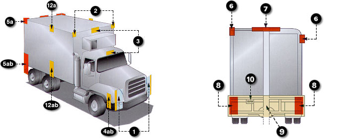
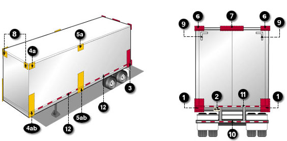
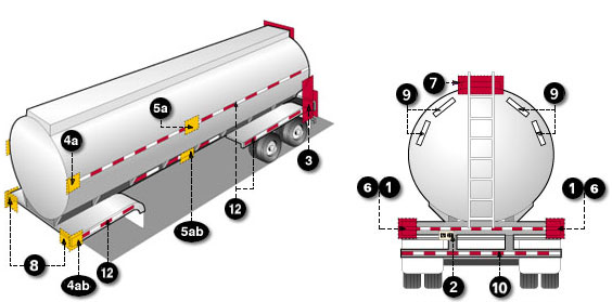
The first column in the “Description” section describes the area under consideration. The first example in the chart refers to area 1. If you look at the illustrations of trailers across the bottom of the page, you’ll see where area #1 is located.
In the second column, the equipment description is “Tail Lamps.”
The third column contains an SAE lens code that you’ll find molded into a properly designed lens. This describes the function of the lighting device as designated by the Society of Automotive Engineers (SAE), an industry professional group. The value of this permanent reference is that it helps to avoid mix-ups where two devices may appear similar, but function differently.
The fourth column describes the purpose of the device and the role it plays in the lighting system. In this case, it is to indicate the trailer’s presence and width.
Mandatory Requirements
The “Mandatory Requirements” section provides information about how to use the devices identified in the “Description” section. Under “Mandatory Requirements” on the chart, the first column tells how many are required. The second column shows which colors are allowed. The third column indicates the location on the trailer body. The fourth column tells you how high the equipment shall be installed, as measured from the ground.
Reading across the seven columns shows the exact requirements under the provisions of FMVSS-108. Simply using the same approach for the remaining equipment would offer a comprehensive picture of the required
equipment.
If a trailer is longer than 30 feet, refer to lines 5a and 5b under the heading “Length 9.1 m (30 ft) or longer.” If a trailer is wider than 80 inches, refer to lines 6, 7 and 8 under the heading “Width 2,032 mm (80 in) or wider.”
Also, if the gross vehicle weight is 10,000 lbs or more, the bottom section of the chart applies. These requirements are shown in a slightly different but similar format.
This last section of the chart refers to the application of “conspicuity tape.” It’s a very rugged tape consisting of highly reflective strips of alternating colors used to make a trailer easier to see. It’s used along with electric lights but greatly enhances the trailer’s visibility.
In the conspicuity section there is a “Description” section as well as a “Mandatory Requirements” section The Mandatory Requirements section calls out the Department of Transportation (DOT) code for the tape locations and the quantity of material to be used. The other columns indicate color, location, height and any options involved in the application.
To help the visualization process, a location drawing at the bottom provides a visual resource for all of the equipment including conspicuity tape. It shows the locations described in the chart.
Trucks, Busses & MPVs
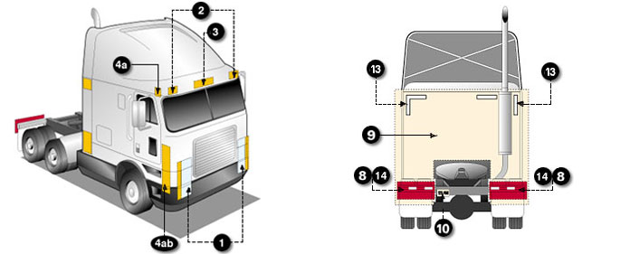
The same process is used to determine requirements for use of lighting and conspicuity markings on trucks and truck tractors to meet the requirements of FMVSS-108.
The practical use of the chart really becomes obvious in situations where a customer needs a replacement for a missing or damaged device.
Let’s consider the example of a stop lamp.
Description
First, find the description for stop lamps. The first column describes the area where the device is located. If you look at the illustrations of the trucks across the bottom of the chart, you’ll see where these areas are located. Stop lamps are in area 8.
The second column lists the equipment. Once you’ve located area 8, you’ll find that stop lamps are the second piece of equipment listed.
The third column contains the SAE lamp code (as a crosscheck with the suggested replacement).
The fourth column indicates the function of the device.
Mandatory Requirements
The “Mandatory Requirements” section provides the same information contained on the chart used for trailers. The first column tells how many devices are required. The second column shows which colors are allowed. The third column indicates the location on the trailer body. The fourth column tells you how high the equipment shall be installed, as measured from the ground.
Using these two charts together, your job of outfitting a truck and trailer safely and legally will be greatly simplified.
Basic equipment required on all trailers
| D E S C R I P T I O N | M A N D A T O R Y R E Q U I R E M E N T S | ||||||
|---|---|---|---|---|---|---|---|
| Area | Equipment | (SAE Lens Coding) | Functional Purpose | Quantity | Color | Location | Height mm (in.) from the ground |
| Tail Lamps | (T) | Indicate vehicle's presence and width | Minimum 2 | Red | On the rear - symmetrical - as far apart as practicable | 380-1830 (15-72) | |
| Stop Lamps | (S) | Indicate braking | Minimum 2 | Red | On the rear - symmetrical - as far apart as practicable | 380-1830 (15-72) | |
| Rear Turn Signal Lamps | (I) | Indicate direction of turn | Minimum 2 | Red or Yellow | On the rear - symmetrical - as far apart as practicable | 380-2110 (15-83) | |
| Rear Reflex Reflectors | (A) | Indicate vehicle's presence and width | Minimum 2 | Red | On the rear - symmetrical - as far apart as practicable- facing rearward | 380-1530 (15-60) | |
| License Plate Lamp(s) | (L) | Illuminates license plate | Minimum 1 | White | On the rear - above or at the sides of license plate | No requirement | |
| Rear Side Marker Lamps | (P2,PC* or P3, PC2*) *photometrically certified at installation angle | Front and rear side marker lamps / side reflex reflectors indicate vehicle's presence and length | Minimum 2 | Red | Each side at rear - as far back as practicable | 380-1530 (15-60) no max. for veh. under 2.032m(80") wide |
| Rear Side Reflex Reflectors | (A) | Minimum 2 | Red | Each side at rear - as far back as practicable facing sideward | 380-1530 (15-60) | ||
| Front Side Marker Lamps | (P2, PC* or P3, PC2*) * photometrically certified at installation angle | Front and rear side marker lamps / side reflex reflectors indicate vehicle's presence and length | Minimum 2 | Yellow | Each side at front - as far forward as practicable | 380 (15) minimum | |
| Front Side Reflex Reflectors | (A) | Minimum 2 | Yellow | Each side at front - as far forward as practicable facing sideward | 380-1530 (15-60) | ||
Length 9.1 m (30 ft.) or Longer
| D E S C R I P T I O N | M A N D A T O R Y R E Q U I R E M E N T S | ||||||
|---|---|---|---|---|---|---|---|
| Area | Equipment | (SAE Lens Coding) | Functional Purpose | Quantity | Color | Location | Height mm (in.) from the ground |
| Intermediate Side Marker Lamps | (P2 or P3) | Indicate presence of a long vehicle | Minimum 2 | Yellow | Each side near center - facing sideward | 380(15) minimum | |
| Intermediate Side Reflex Reflectors | (A) | Indicate presence of a long vehicle | Minimum 2 | Yellow | Each side near center - facing sideward | 380-1530 (15-60) | |
Width 2.032 m (80 in.) or Wider
| D E S C R I P T I O N | M A N D A T O R Y R E Q U I R E M E N T S | ||||||
|---|---|---|---|---|---|---|---|
| Area | Equipment | (SAE Lens Coding) | Functional Purpose | Quantity | Color | Location | Height |
| Rear Clearance Lamps | (P2, PC*or P3, PC2*) * photometrically certified at installation angle | Show vehicle's width - MAY NOT be combined with tail lamps | Minimum 2 | Red | At widest point - symmetrical - on the rear or near the rear - facing rearward | As high as practicable - may be lower only if ID lamps are at the top | |
| Rear Identification Lamps | (P2 or P3) | Indicate presence of a wide vehicle | Exactly 3 | Red | On the rear - center, facing rearward - horizontally spaced 150 mm (6 in.) to 300 mm (12 in.) apart | in Canada : at the top - maybe lower if door header narrower than 25 mm in USA: as high as practicable |
| Front Clearance Lamps | (P2, PC*or P3, PC2*) * photometrically certified at installation angle | Show vehicle's width | Minimum 2 | Yellow | At widest point - symmetrical - as far forward as practicable - facing forward | As high as practicable | |
Width 2.032 m (80 in.) or Wider and GVWR 4536 kg (10,000 lb.) or More
| D E S C R I P T I O N | M A N D A T O R Y R E Q U I R E M E N T S | ||||||
|---|---|---|---|---|---|---|---|
| Area | Conspicuity Treatment | DOT Coding | Quantity | Color | Location | Height | OPTIONS |
| Rear Upper Body Marking | DOT-C, DOT-C2, DOT-C3, or DOT-C4 | Exactly 2 pairs of 300mm long strips | White | On the rear upper corners - facing rearward | At the top | Reflex reflectors may not be required if they are replaced, in their required location, with conspicuity treatment Optional in Canada Rear lower body and side conspicuity treatment may also be solid white, solid yellow, or white and yellow. | |
| Bumper Bar Marking | Continuous | Red/White | On the rear bumper bar's horizontal element - full width - facing rearward | No requirement | |||
| Rear Lower Body Marking | DOT-C, DOT-C2, DOT-C3, or DOT-C4 | Continuous | Red/White see options | On the rear - full width of the vehicle - facing rearward | As horizontal as practicable and as close as practicable to the range of 375 to 1525 mm from the ground | |
| Side Marking | see location | Red/White see options | Each side - facing sideward - continuous, or evenly spaced over minimum of 50% of length, starts and ends as close to the front and rear or vehicle as practicable | As horizontal as practicable and as close as practicable to the range of 375 to 1525 mm from the ground | |||
IMPORTANT NOTE: Every lamp, reflex reflector, and conspicuity treatment (device) must be permanently attached in the location specified below and must comply with all applicable requirements prescribed for it by FMVSS/CMVSS 108. The face of any device on the front/rear and sides should be, respectively perpendicular and parallel to vehicle centerline, unless it is photometrically certified at installation angle. No part of the vehicle shall prevent any device from meeting its prescribed requirements unless an auxiliary device meeting all prescribed requirements is installed.
IN CANADA: Manufacturers and importers of vehicles must have the proper certification test records demonstrating compliance of lighting components with all prescribed requirements.
Use the self assessment below to gauge your understanding of this section. Place your answer in the box and then check your answer by clicking on the "show answer" link.
Or, you can skip the assessment.
Instructions:
Read the question.
Place your answer in the box.
Example:
True or False:
You should read the questions and then type your answer into the box.
show answer
True!
Begin:
1. True or False: “Most distant point” refers to the distance from the source of power to the farthest circuit device measured in the most direct way possible.
show answer
False
2. True or False: To determine the amount of current a circuit will draw, add together the current draw for all of the devices that will be attached.
show answer
True
3. True or False: On the wire size chart, the load in amps is displayed across the top of the chart.
show answer
False
4. Heat causes resistance to _____.
show answer
a) Increase
5. The main set of rules that govern truck and trailer lighting comes from:
show answer
a) NHTSA
6. On the FMVSS-108 chart, which of the following is not specified:
show answer
c) Size of light
7. True or False: Under the “Basic Equipment Required On All Trailers” a minimum of two reflectors is required on the rear.
show answer
True
8. True or False: For a trailer over 80 inches, three or four rear identification lamps are required.
show answer
False
9. On a 29 foot trailer, how many intermediate side marker lamps are required?
show answer
d) None of the above
10. True or False: According to FMVSS-108, license plate lights must be mounted above the plate.
show answer
False
11. True or False: On an 80 inch wide trailer, the rear clearance lamps are often combined with tail lamps to save space.
show answer
False
12. True or False: When applying conspicuity tape on the side of a trailer, it must cover at least 50% of the length of the trailer.
show answer
True