
When you have successfully completed this section, you will have mastered the following:
Typical electrical system
In the earliest days of the automobile, the electrical system was simple. It was just used to ignite the fuel/air mixture in the crude internal combustion engines. Starting the engine was the job of the driver or passenger and a hand crank. Lights were just acetylene lanterns, if there were lights.
By the end of the 1920s, electric starters had replaced hand cranks, electric headlights had replaced lanterns and electric horns had taken over for the hand-squeezed air horn. Today, vehicles operate with complex and extensive electrical systems with many circuits and devices that produce, store and distribute electricity.
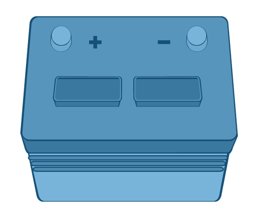 The main component of the electrical system is the battery, which is the initial source of electricity for all the rest of the on-board systems for most vehicles. The battery is used as a storage device, supplying the power required to start the engine and operate the other systems such as clocks, alarms, radios and others while the engine is off.
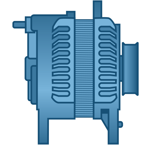
The second key component in the electrical system is the alternator. It is powered by the engine and has two main functions:
Along with the alternator, the charging system also includes a voltage regulator to protect onboard devices (including lights) from the effects of higher-than-specified electricity flow. Light bulbs are susceptible to higher-than-normal current levels that cause filaments to age almost instantly and "burn-out".
The alternator (or as it is technically known, alternating current generator) uses the same general approach as other generating devices in that it depends upon electromagnetism to create an electrical current. It does so by moving one magnetic field, called a rotor, inside a fixed electromagnet called a stator. The alternator is driven off of the engine through a belt arrangement much the same as a water pump. Mechanical energy from the engine is converted to electrical energy by electromagnetic induction (creation of a magnetic field).
The rotor consists of a coil of wire wound around an iron core, which is pressed onto a steel shaft. The stator has similar windings that create an electromagnetic field in the rotor as it spins.
The electrical energy created by the alternator is AC or alternating current. In order to be useful in a vehicle system, it must be changed to DC or direct current. That is done through the use of devices known as diodes. Diodes polarize the AC output into DC output. This process is sometimes referred to as rectifying the current. Hence, the assembly that holds the diodes is often called a rectifier.
The alternator also has built-in controls that limit its output. The regulator circuits protect the battery and the rest of the electrical system from too much output.
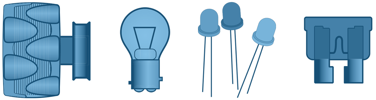
The starter is another basic component of the vehicle electrical system. Although it has evolved over the years into an efficient and reliable device, the starter still functions much the same as the earliest ones. It spins the engine to a sufficient speed to sustain ignition in both internal combustion and diesel engines.
Lighting is an important function of the electrical system. Most vehicle lighting operates on the same basic principles as the starting, ignition and charging systems. The vital components include the lighting sockets, bulbs or LEDs, connectors, wire and cable, switches, fuses, alternator and battery. It also includes the metal frame of the vehicle itself, which acts as the ground, becoming part of the lighting circuits. The use of the metal frame allows what can be referred to as "one wire" systems.
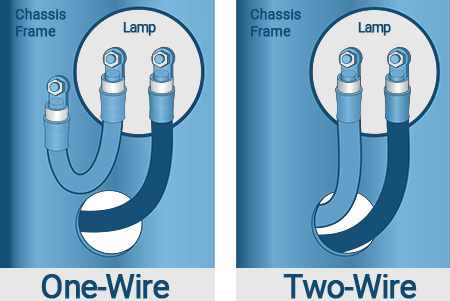 They are called that because typically, an electrical circuit requires a "supply" wire which carries current to the load (device requiring electrical energy) and a return wire to complete the circuit. With a vehicle system using the metal frame as the ground, that second connection isn’t required. The battery ground wire is attached to the frame. The ground wire of any individual device can simply be attached to the metal frame at a convenient spot.
It’s important to remember that in order for the frame to effectively provide a complete circuit, there must be good contact between the wire from the system devices and the metal of the frame.
There has to be good metal-to-metal contact and a strong mechanical connection including the use of screws.
Because the battery is such a pivotal part of the lighting it is worthwhile to look at it a little closer.
The primary function of the battery is to provide starting energy for the vehicle and electrical power for critical systems and devices when the engine and alternator are shut down. It also acts as a stabilizer for voltage throughout the system. Modern batteries are built to withstand the primary causes of early failure: extremes of weather, severe vibration, engine heat, corrosion, extreme discharge and prolonged periods of inactivity.
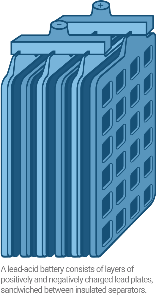
Typical vehicle batteries consist of layers of positively and negatively charged lead plates. Those, along with their insulated separators, make up each of a 12-volt battery’s six, 2-volt cells. They are typically made of wire mesh coated with porous lead.
These lead-acid batteries are filled with a conductive liquid called electrolyte, a mixture of two-thirds distilled water and one-third sulfuric acid. The spaces between the plates are filled with the electrolyte and the plates are exposed. The interaction of the plates and the electrolyte produces chemical energy which, when electrical devices are connected to the positive and negative terminals, is transformed into electric current. When the battery has given up its charge to the lights and other components of the electrical system, the alternator can send electrical power to the battery, which in turn converts the input to chemical energy until the vehicle needs it again.
Wire & cable basics
Wire and cable are fundamental to the use of electricity. Some basic fundamentals of construction and how they work will help make the correct choice easier and more efficient.
First is construction. A typical wire or cable in use today has a relatively simple construction. There are two major components:
Of course, there are exceptions. A battery ground strap, the device that connects one terminal of a battery to the frame of the vehicle, often consists
of a "woven" metal construction. That particular design requires no insulation.
 Other types of cables, such as some styles of spark plug wires, require a substantially more complex construction and insulation to defeat Radio Frequency Interference (RFI) generated by current flow. But these are the exceptions. The vast majority of vehicle wiring is done with more basic types of wire and cable.
Typically, the manufacture of a wire or cable is as simple as coating a conductor with a layer of insulating material. This material is referred to as "dielectric" because of its lack of current carrying capacity. The measurement of the insulating ability of a given material is referred to in terms of its dielectric strength.
 Many materials are not good conductors. In fact, the poorest conductors make the best insulation materials. The difference between an insulator and a conductor is that insulators have few, if any, free electrons-those that are ready to travel from an area full of electrons to an area with less.
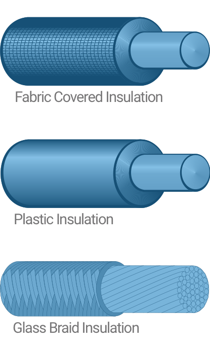
Insulators are made up of atoms that have electrons that are tightly bonded to them. In the past, many materials have been used as insulators in electrical systems. Rubber, cloth, paper, woven silk, glass and a number of other materials have been tried.
Before the advent of plastics, many forms of insulation were tried. Even lacquer, the same kind used to finish wood, was applied to metal conductors. However, lacquer scratches easily and was easily worn off.
After World War II a whole new generation of insulation material was created. Plastics have good dielectric strength, flexibility, abrasion resistance and resistance to chemicals. Today, insulation is made from PVC, polyethylene, and a variety of other plastics.
In wire applications, insulation plays several roles. The basic role is to separate the conductor from its surroundings and especially shield it from reaching a ground accidentally. The insulation helps maintain the intended path and prevents a short circuit or a grounded circuit.
 Since insulation often has a color associated with it, it can help identify a particular wire when tracing a circuit. That makes it easier to keep electrical systems organized, especially when troubleshooting or making repairs.
Conductors are the opposite of insulators in their operating characteristics. Atoms in good conductors have an abundance of "free" electrons compared to insulators with few, if any. Examples of ordinary conductors are: copper, iron, aluminum, lead and steel.
Of the conductors, platinum, gold and silver are excellent, but they are expensive to use and are typically only found in high value applications, such as computers. In that type of use, a highly-efficient conductor is required because voltages are low ("pressure" pushing current is low). A good conductor helps to keep the electricity flowing.
Copper, on the other hand, is a very affordable conductor. That’s why copper wire is so common.
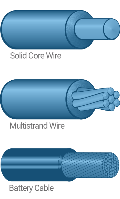
Conductors may be single strand or a group of strands. Stranded conductors are preferred in
heavier gauges because they are more flexible and easier to work with than a comparable single strand conductor.
Comparing stranded cable sizes is simple. Stranded cable is compared using a numerical system. For example, 18/24 indicates that the conductor consists of 18 strands of 24-gauge wire.
Similarly 12/12 refers to 12 strands of 12-gauge wire.
Gauge refers to the size of the conductor in a wire. The higher the gauge number, the smaller the wire. For example, an 18-gauge wire is smaller than a 12-gauge wire. And a 4-gauge wire has more than twice the diameter of a 10-gauge wire.
When the wire size gets larger, the number reaches #0 gauge or 1/0 (one aught). Additional zeros refer to larger sizes. The next larger size above 1/0 is #00 or 2/0 (Two aught).
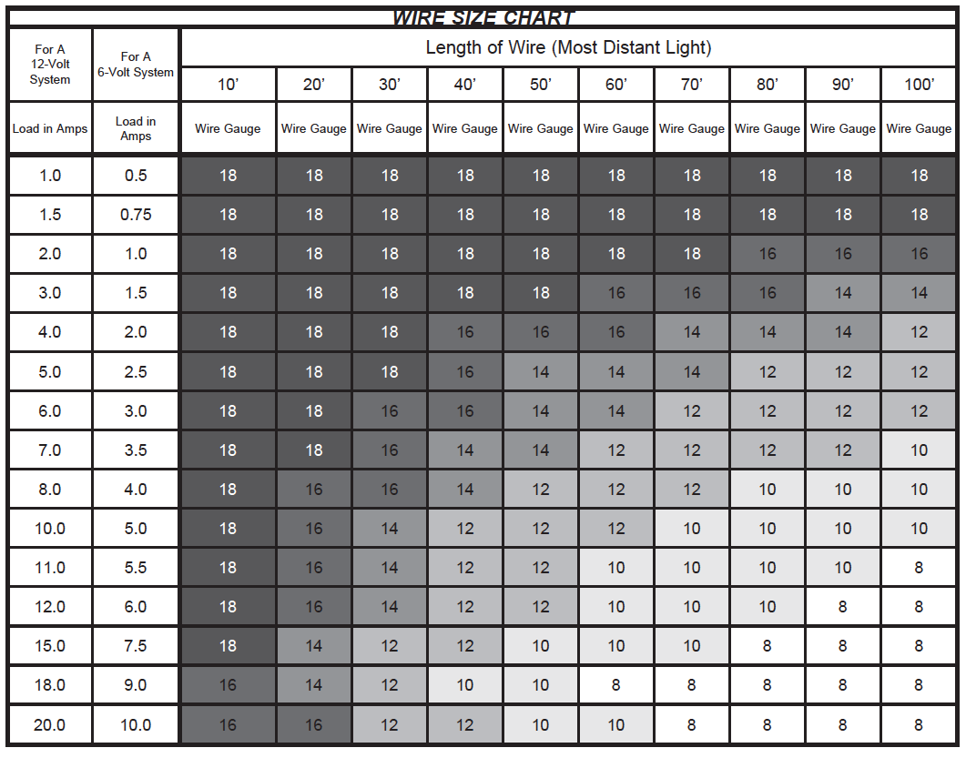
The capacity of a wire reflects the ability it has to carry electrical current. For example, over a distance of 50 feet, a 12-gauge wire can safely carry 10 amps. Over the same distance a 16-gauge wire can carry 3 amps. Choosing the right size wire is made easier using the Grote wire size chart found in the Grote Reference Guide.
Wire Gauge Chart
A.W.G. = American Wire Gauge
S.W.G = Imperial Standard Wire Gauge (British legal standard)
GAUGE |
S.W.G. |
A.W.G. (inches) |
A.W.G. (mm) |
Actual Size (A.W.G.) |
|---|---|---|---|---|
00 |
0.348 |
0.368 |
9,266 |
 |
0 |
0.324 |
0.325 |
8,252 |
 |
1 |
0.300 |
0.289 |
7,348 |
 |
2 |
0.276 |
0.258 |
6,543 |
 |
3 |
0.252 |
0.229 |
5,827 |
 |
4 |
0.232 |
0.204 |
5,189 |
 |
5 |
0.212 |
0.182 |
4,621 |
 |
6 |
0.192 |
0.162 |
4,115 |
 |
7 |
0.176 |
0.144 |
3,665 |
 |
8 |
0.160 |
0.129 |
3,264 |
 |
9 |
0.144 |
0.114 |
2,906 |
 |
10 |
0.128 |
0.102 |
2,588 |
 |
11 |
0.116 |
0.091 |
2,304 |
 |
12 |
0.104 |
0.081 |
2,052 |
 |
13 |
0.092 |
0.072 |
1,829 |
 |
14 |
0.080 |
0.064 |
1,628 |
 |
15 |
0.072 |
0.057 |
1,450 |
 |
16 |
0.064 |
0.051 |
1,291 |
 |
17 |
0.056 |
0.045 |
1,150 |
 |
18 |
0.048 |
0.040 |
1,024 |
 |
19 |
0.040 |
0.036 |
912 |
 |
20 |
0.036 |
0.032 |
813 |
 |
21 |
0.032 |
0.029 |
724 |
 |
22 |
0.028 |
0.025 |
643 |
 |
It’s important to remember that wire size is dependent upon the conductor size, not the outside dimensions. A cable using a 4-gauge conductor would have more than twice the capacity of a 10-gauge conductor with a heavy insulating layer, which might give it the same outside diameter.
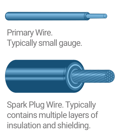
There are two types of wire used on a vehicle: Primary and Secondary.
Primary wire refers to conductors used as part of the vehicle’s electrical system.
Secondary wire is used as part of the so-called secondary circuit of the ignition system. That circuit consists of the coil secondary winding, the coil wire, the distributor cap, sparkplug wires, and spark plugs. A major characteristic of secondary
wiring is that it carries high voltage. In some cases, it can exceed 50,000 volts.
Primary wire refers to most of the other wire found in the vehicle. It’s reported that the typical auto contains over a mile of primary wire, with more added as cars become more complex. It can be found on parts of the ignition system and includes battery cables (relatively low voltage).
However, the majority of the primary wire is used for connecting lights and other types of onboard equipment. As such, primary wire typically carries 12-14 volts. The current it carries can vary from a few milliamps (thousandths of an amp) to as high as 100 amps.
Primary wire can be either single or multi-strand conductor surrounded by an insulating layer. As with other wire types, the function of the conductor is to provide a pathway for the passage of the current. The insulation keeps the electrons from escaping. Grote primary wire is supplied in a number of types and sizes from 18 to 4/0 gauges.
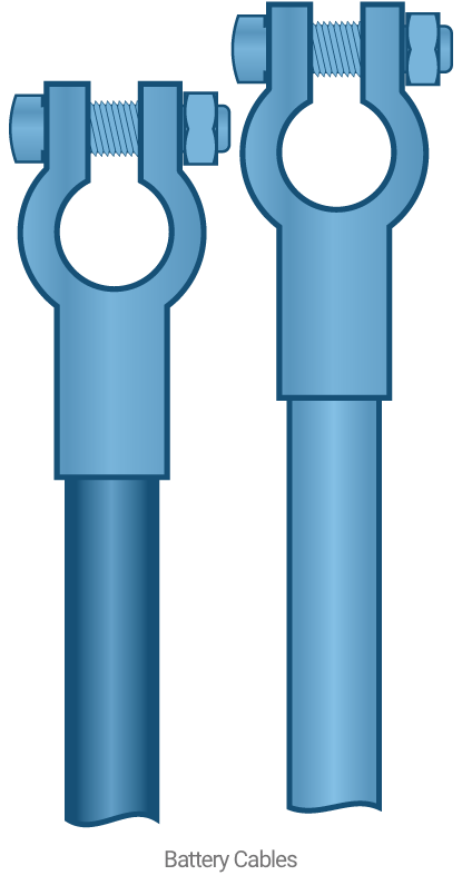
Battery cables represent a special type of wire and cable utilizing stranded conductors and heavy fittings because of the amp loads they are required to carry. The voltage is usually modest, around 12 volts. But amperage can climb as high as 100 when powering up devices such as starter motors. This
is the opposite of what occurs with a spark plug, which uses high voltage to drive a relatively low level current across the gap in the plug. The battery cable has a heavy conductor and modest insulation layer. A sparkplug wire has a relatively small conductor with a substantial insulation layer.
Battery cables have several components. First is the cable itself. It is made up of many strands of copper wire surrounded by a layer of dielectric material. The insulating layer’s function is to protect the cable from shorting out while keeping away moisture that could cause corrosion.
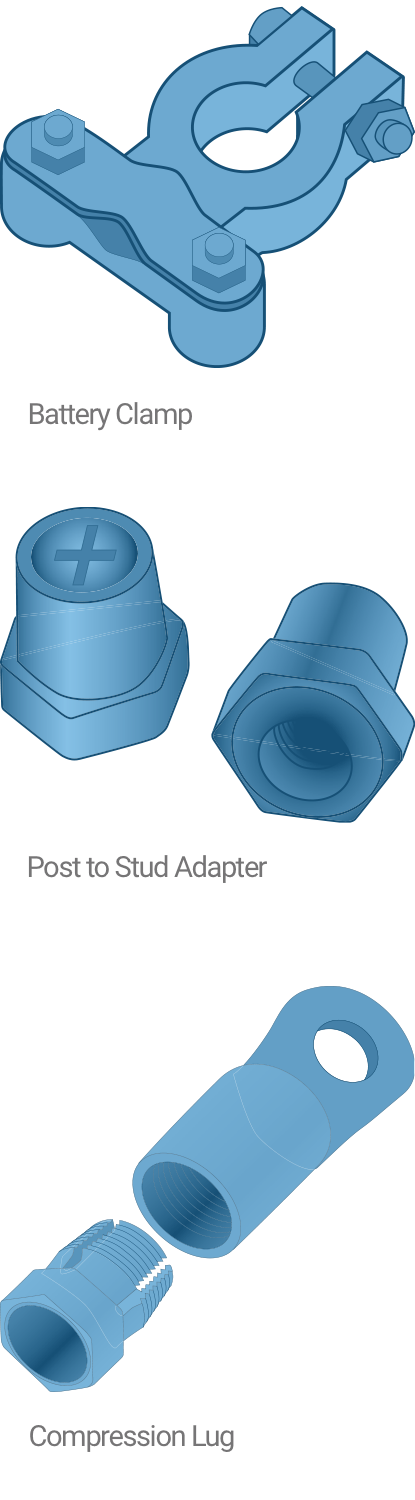
At one end of the cable is a terminal that connects to the battery. Although there are many variations of terminals, the most common is still the "y" connector that fits over the terminal stud on the battery and clamps on to provide the most secure and efficient contact between cable and battery.
At the other end of the cable is a lug designed to connect the battery to a starter motor. The lug has a hole that fits over a stud on the starter motor and gets tightly attached with a wrench.
There are many variations of these basic connectors. For example, the Grote Quick® compression
fittings are easy-to-use fittings that utilize a threaded insert that provides a secure, efficient connection without torch, solder or crimping tool.
Specialty fittings add utility to batteries. For example, Grote supplies a battery post to stud connector that provides a quick disconnect feature to prevent battery drain over long periods of inactivity. Top post to side post converters change the connecting points on the battery from top access to side access. For multi-battery setups, QuickHarnesses® allow connecting two or three separate batteries to be teamed in a parallel circuit to provide maximum starting power at the same voltage.
No matter what the variety, choosing the correct wire size for the application is critical. The key information required is the length of wire required, often referred to as the length of run, and the current load that the conductor is expected to carry in use. Knowing the “length and load” characteristics will take the guesswork out of the choice.
Voltage drop is the primary consideration when selecting the proper conductor size. Every conductor has a certain amount of resistance per foot. The longer the distance, the greater the resistance in the circuit. As distance from the power source increases, there is less voltage available to “push” the current through the wire and the current drops. There is also heat buildup as the resistance increases, also lessening the amount of current flow.
In low voltage systems, such as vehicles, even a small drop in voltage can have a serious effect. But there’s a simple solution. As you get further away from the power source, make the conductor larger. A larger conductor means less resistance.
Calculating the length of run requires a measurement referred to as the “most distant point.” Care must be taken to calculate the actual length. That means allowing for connections, providing slack to reach around obstacles and generally making sure that the length of run is not understated. For example, a rear trailer light mounted in the center might need to be fed from the side instead of down the center. That extra run could double the length of the wire.
Calculate The Actual Length Of Each Wire Run
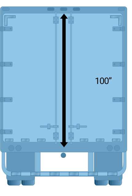
There may be 100” between the point where the wiring harness terminates (below the floor of the trailer) and the lights (above the door) that you wish to connect.
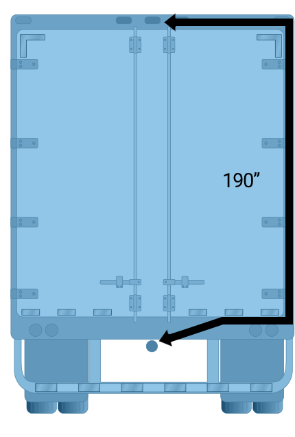
The wire must be routed over to the side of the trailer, up the wall, and back across the ceiling to the lights.The actual run is closer to 200”.
With the length of run known, calculate the required amount of amps by adding together the draw for all of the devices that will require power on that circuit. With the two calculations complete, the correct wire size can be calculated.
Using the “Wire Size” chart below, first find the load in amps on the left-hand edge of the chart. Choose the column that reflects the system used on the vehicle (6 volt or twelve) and go down the column to the amp load calculated.
Then find the length of run across the top of the chart. Read down that column until it intersects with the amp load line. The point at which they cross indicates the correct wire size for the job.
Since heat has the effect of increasing resistance and diminishing the capacity of the wire to carry current, it makes sense to determine the possible effect that the operating temperature might have on the wire choice.
To do that, find the suggested wire size (from the prior exercise) on the left edge of the “Temperature Chart” at the right. On that line, read across to the temperature column that reflects the operating environment. At that intersection, read the maximum allowable amp carrying capacity. Confirm that the maximum amp load indicated is greater than or equal to the load in the new circuit. If not, choose a heavier gauge and once again check the temperature chart.
TEMPERATURE CHART
Maximum Current Carrying Capacity (For 12 Volts at Listed Temperatures)
Cable Size |
120° F |
125° F |
150° F |
|---|---|---|---|
20 Gauge |
15 Amps |
13 Amps |
9 Amps |
18 Gauge |
18 Amps |
15 Amps |
11 Amps |
16 Gauge |
22 Amps |
19 Amps |
14 Amps |
14 Gauge |
27 Amps |
23 Amps |
17 Amps |
12 Gauge |
40 Amps |
32 Amps |
24 Amps |
10 Gauge |
50 Amps |
42 Amps |
31 Amps |
Note: Currents above those listed may increase the temperatures of the PVC above a safe design level of 180° F.
NOTE: The charts on this page also appear in the “Technical Information” section of the Grote Reference Guide.
Use the self assessment below to gauge your understanding of this section. Place your answer in the box and then check your answer by clicking on the "show answer" link.
Or, you can skip the assessment.
Instructions:
Read the question.
Place your answer in the box.
Example:
True or False:
You should read the questions and then type your answer into the box.
show answer
True!
Begin:
1. True or False: The first cars used simple electrical devices for starting and for lighting the way over crude roads.
show answer
False
2. True or False: The main component of the vehicle electrical system is the spark plug.
show answer
False
3. Which of the following is not a prime function of the alternator?
show answer
d) Drive the water pump
4. Alternators rely on to create electrical current.
show answer
b) Electromagnetism
5. True or False: The rotor on an alternator is wrapped in a non-conducting material.
show answer
False
6. The part of the alternator, which is fixed in place is referred to as the:
show answer
d) Stator
7. True or False: The vehicle starter turns at a rapid rate in order to generate the electricity required to start the engine.
show answer
False
8. The “one wire” system is one that:
show answer
d) Uses the frame of the vehicle as a ground, doesn’t require a ground wire
9. At 120° F, the maximum amperage that an 18 gauge wire should carry is:
show answer
b) 18 Amps
10. True or False: A battery post to stud connector provides a quick disconnect feature to prevent battery drain over long periods of inactivity.
show answer
True
11. True or False: Typical batteries are made up of negatively charged plates separated from positively charged plates by insulated separators.
show answer
True
12. Batteries are filled with a special liquid known as
show answer
c) Electrolyte
13. The interaction between the plates and liquid in a battery produces
show answer
b) Chemical energy
14. True or False: A typical wire or cable uses a wire core surrounded by a conductor.
show answer
False
15. True or False: The end of a battery cable that connects to the starter motor post should be terminated with a spade connector.
show answer
False
16. Wire and cable insulating material is sometimes referred to as _______ because of its lack of current carrying capacity.
show answer
d) Dielectric
17. True or False: The atoms of conductors have a great many electrons loosely bonded to them, ready to leap to the next atom, whereas insulators typically have few if any.
show answer
True
18. True or False: Gold and silver are used in critical applications that require a highly efficient conductor because the voltages are low, the connections must be sure and the value of the device is relatively high as in computers and other electronics.
show answer
True
19. When using a stranded conductor, what do the numerals “18/24” stand for?
show answer
c) The quantity and gauge of the strands
20. True or False: When measuring wire gauge, 4 gauge wire is more than twice the thickness of 10 gauge.
show answer
True
True or False: Wire gauge larger than whole numbers is shown as 1/0.
show answer
True
22. Secondary wire is used as part of the secondary circuit of the ignition system. Which of the following is not part of the secondary system?
show answer
c) Battery
23. True or False: Primary wire is used to connect devices including radios, lights, heaters, etc.
show answer
True
Primary wire typically carries:
show answer
b) 12-14 volts
25. True or False: Most primary wire is a single conductor with an insulating layer.
show answer
True
26. True or False: When calculating the length of a wire run, you must allow for connections, providing slack to reach around obstacles and generally make sure that the length of run is not understated.
show answer
True
27. The most important consideration when choosing a wire or cable size is:
show answer
c) Voltage drop
28. True or False: For the same length of wire, the larger the conductor, the greater the resistance.
show answer
False
29. “Most Distant Point” refers to:
show answer
b) Location of the light furthest from the power source