
When you have successfully completed this section, you will have mastered the following:
The discovery of electricity changed the world. Electrical power offered inexpensive and convenient energy for homes and businesses for the first time in history. It has also made possible the internal combustion engine and many of the functions we take for granted on the cars and trucks we drive. Electricity is used to start them and keep them running. It’s especially important for the lights and signals that are required on vehicles for safety and convenience. This section of the Grote Know-How Self Study Guide is devoted to understanding the basics of electricity... what it is and how it works.
How electricity is created
Electricity is based on the interaction of the components of atoms, the basic elements that make up everything around us. Atoms have a nucleus, a center cluster of “protons” and “neutrons.” The nucleus is surrounded by orbiting (circling) elements known as “electrons”.
Protons have a positive charge. Neutrons are neutral – no charge. Electrons have a negative charge.
Normally, an atom has the same number of protons and electrons. With the same number of positive and negative charges, the atom is balanced. It’s neither positive nor negative.
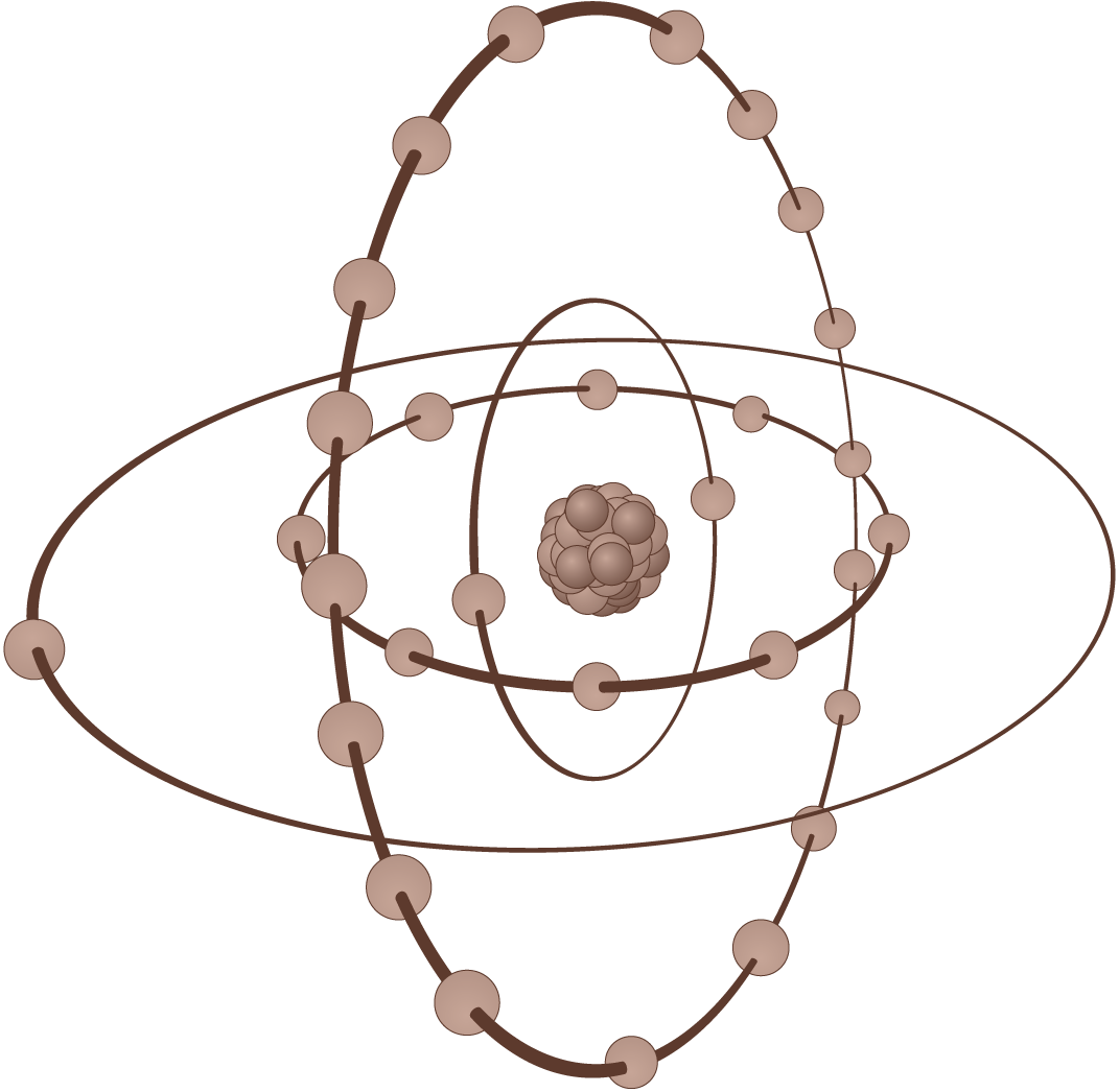
The electrons orbit the nucleus in layers or shells. In the copper atom, shown at the right, the inner shell has two electrons. The second shell has eight electrons. The third shell has 18 electrons. The outside or “valence” shell has one electron. Electrons in the valence shell are called valence electrons.
Bring a strong negative charge (like the negative terminal of a battery) close to a copper atom, and that single valence electron can be encouraged to break free from its orbit and head for a new orbit in a nearby atom.
But now the new atom has one too many electrons. So one of them will break free and head for yet another atom. The movement of these free electrons from atom to atom is called electricity.
Remove the strong negative charge that started all of this, and the flow of electricity stops.
The valence shell of an atom can hold, at most, eight electrons. The more electrons in the valence shell, the more stable they will be. They won’t easily jump from one atom to the next. Such materials are insulators.
Conductors: Atoms with 1 or 2 valence electrons
Semiconductors: Atoms with 3 to 5 valence electrons
Insulators: Atoms with 6 to 8 valence electrons
Practical electricity
For electricity to be of use it must be harnessed and controlled to do work, such as powering a light or motor. Transferring electricity from an electron source to the device that needs it is the job of a conductor or wire.
There are three basic characteristics of electricity that are interrelated and control the work of electrical energy.
OHMS: The resistance or friction encountered by the current pushed through the wire.
VOLTAGE: The pressure that pushes electricity through a wire.
AMPERAGE: The current load or volume of electricity through a wire.
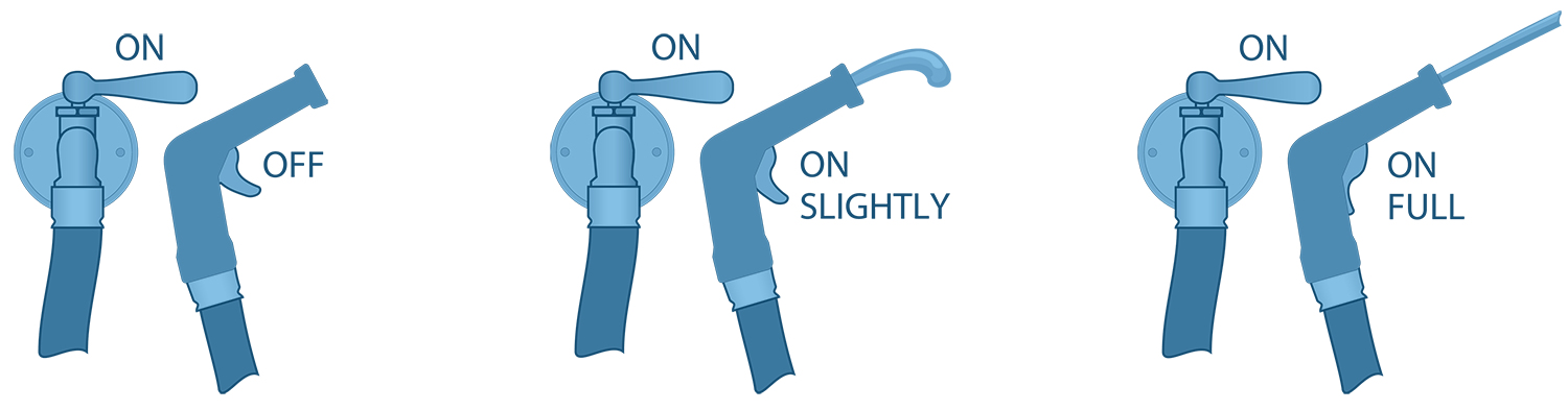
Understanding the relationship is easier by thinking of the wire as a hose that is connected to a spigot at one end and has an adjustable nozzle at the other end. Starting with the spigot turned on and the nozzle closed, water can’t flow and the pressure is at its maximum inside the hose.
When the nozzle is opened slightly (ohms of resistance lowered) the water pressure (voltage) pushes a small amount of water (current) through the hose at a high pressure sending it a considerable distance. If the nozzle is opened wide (resistance lowered more), the flow of water (current) is greater but the pressure (voltage) is lower and the stream is much shorter.
Although not exactly the same as water through a hose, the effect is similar for electricity through a wire. Voltage is the result of an over-supply of electrons seeking an area with relatively fewer electrons. The greater the difference, the greater the pressure or voltage.
The electrons, when flowing, are referred to as amperage or amps, and the more that move through the wire or conductor the higher the amperage is said to be. And while it may seem that one amp is not very much, it requires the passage of 6 billion electrons/second to create that one amp. One amp at one volt will power a one watt bulb. In a 12-volt system, one amp will light a 12-watt bulb. The resistance to the passage of electrical current is measured in ohms. Resistance is caused by the energy absorbed when electrons break free and move to another atom.
It’s important to understand the relationship between volts, amps and ohms. That relationship is simply stated in a simple formula called Ohm’s law where “I” stands for current, “E” for voltage and “R” for resistance.
E = I x R: To find voltage
I = E ÷ R: To find amperage
R = E ÷ I: To find resistance
VOLTS= AMPX * OHMS
OHMS= VOLTS / AMPS
AMPS= VOLTS / OHMS

Although calculating one of the three measurements using Ohms law is seldom required, it does help understanding what occurs in a vehicle electrical system and how that changes the electrical flow.
For example, cracked or broken strands in the wiring, bad or dirty switch contacts or loose connections all make it harder for current to flow through the system. If the voltage remains the same (for example 12 volts) and the resistance increases because of the deteriorated conditions, the amperage in the circuit will drop. The result will be weak or dim lighting.
On the other hand, if the resistance remains the same, and a malfunction in electrical system allows higher-than-normal voltage to flow, the amperage will rise. That could have a damaging effect on the electrical systems. For example, the excess amperage could overheat the filaments in light bulbs causing them to burn out.
It’s apparent that volts, amps and ohms are interrelated. The rule of thumb simply stated is, it takes one volt to push one amp through one ohm of resistance.
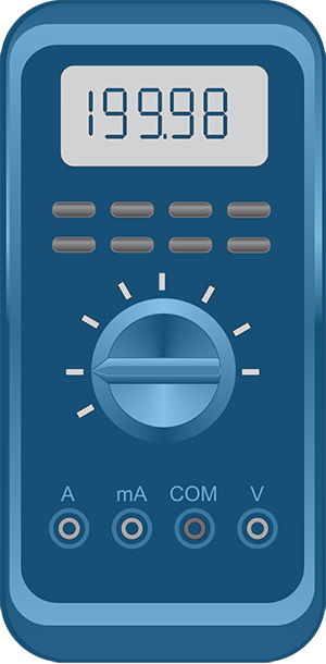
Measuring volts, amps and ohms requires special instruments. For voltage measurements, the instrument is called a voltmeter. Voltmeters may be the traditional swinging needle type or the newer, digital type that reports the measurement values on an alphanumeric display.
Amps are measured using an ammeter. Since it measures the current flow, it must be capable of measuring the minute fractional values as well as the higher levels without damage or injury to the user. Ammeters typically come in two categories. One is the milliammeter, used for milliamperes, which are fractions of an amp and higher amp capacity meters which are teamed with voltage measuring devices known as Voltage/amperage testers, sometimes referred to as “VAT’s.” Milliammeter are often teamed with voltmeters and ohmmeters in a handy unit called a “multi-meter.”
Ohmmeters measure the resistance offered by an electrical circuit. Since, under most circumstances, all conductors offer resistance to the flow of current, and since resistance plays a key role in the function of electrical systems, it’s worth a closer look.
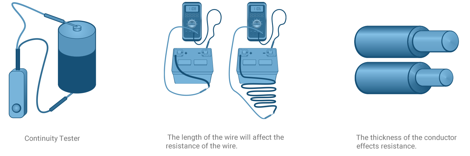
A continuity tester, as the term indicates, checks to see if a circuit is complete or broken between the two points where its leads are connected. It has a battery and a lamp that lights to signal when the circuit is complete. It says nothing about high resistance due to corrosion or a wire that is too small, low voltage or insufficient current. It is merely an "on or off" device.
Even though the continuity tester is equipped with pointed probes, never poke the probe into a wire to check a circuit. Even the tiniest pinhole will let moisture and chemicals in, and the wire will corrode.
Resistance plays a key role in the function of electrical systems. The resistance of any conductor, even of the same material varies along with length, diameter (thickness), material, and temperature. A short wire with the same thickness of a longer wire of the same material at the same temperature will offer less resistance. It’s primarily due to the shorter distance the electrons are forced to travel from the area of high density to an area of less density.
The material has a lot to do with resistance. Copper, for example, gives up its one valence electron easily. So it allows electrons to flow readily. Iron, on the other hand, has two valence electrons. It’s still a conductor. But it doesn’t give up electrons as easily as copper. So iron has more resistance than copper.
Size of wire effects resistance. In general, the flow of electrons through a larger wire is easier than the same flow through a smaller one. Once again, the effect is based upon the availability of electrons.
In most metal conductors, heat increases resistance. Heat causes electrons to become excited and fly off in random directions. That random movement interferes with the orderly transfer of electrons, causing resistance. As the electrons fly around within the conductor, they create additional heat, which creates even more resistance. It’s possible that, in the right temperature and heavy current flow conditions, a wire or cable could cause a fire or fail completely. Resistance is the reason that choosing the right capacity wire and cable is so important.
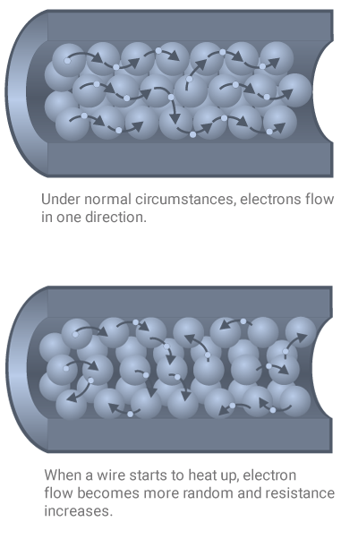
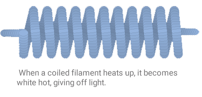
However, resistance is not always a bad thing. For example, the glow of a filament in a light bulb is the result of resistance of current flowing through a specialized metal conductor. As the current passes through it, the filament wire quickly heats up producing a very bright glow. Also, certain types of conductors are designed to produce large amounts of resistance, which produces heat. These resistance-based devices are used in countless applications where heat is required.
Working with electricity
The flow of electricity is fairly simple in both principle and in real life. Nature is constantly attempting to achieve a perfect balance of electrons from one location to another. For that reason, groups of electrons constantly seek a path from areas dense with them to areas where they are less dense. The best and easiest target for these electrons is the earth itself…the ground. Other targets are large masses of metal. For example, the metal frame of a vehicle.
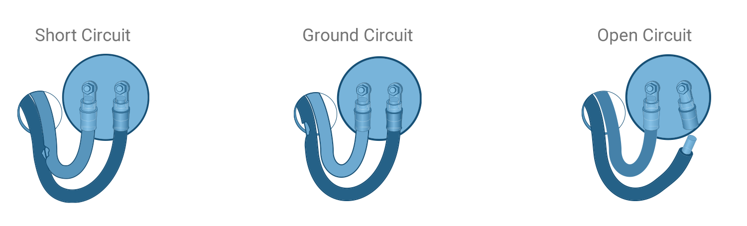
In finding the shortest path, electrons will flow along the easiest possible route. Since resistance slows down and restricts the flow of electrons, they will avoid areas that offer more resistance. They take the so-called “path of least resistance.” Given the opportunity it will seek the ground even though it may not be the path it is supposed to take. One type of unplanned path where the flow of electrons reaches ground before completing its designed task is called a short circuit.
In its most basic form, a short circuit occurs when a bare wire touches another wire that offers a more direct path to the ground than the designed path. The name comes from the fact that the current flow leaves the wire in favor of the other wire taking a shorter path or circuit.
Short circuits are typically caused when the insulation is accidentally removed. This can occur when wire is allowed to rub on a sharp object. Most typical is the case of two wires rubbing together. Both may become abraded until the two bare wires are brought into contact.
A grounded circuit is similar in result to the short circuit. However, in this case, the easier path is directly to the ground, typically a large metal mass such as a vehicle frame. Grounded circuits typically occur when a wire rubs on the frame or component of the vehicle until the bare wire is in contact with the metal. Like the short circuit, the grounded circuit represents a shorter path with less resistance than the designed path.
The open circuit is actually the opposite of the path of least resistance. With the previous two conditions, the result was electrons flowing through the wrong circuits to the ground and not accomplishing the designed work. With an open circuit condition, work is also not done because the electrons never reach a ground point. It is usually caused by a break in the conductor or a wire pulled loose from a terminal or device.
As with resistance, not all cases of open circuits are negatives. A simple switch actually produces an open circuit “on-demand” making it easier to control the flow of electricity from power source to destination.
There are times when an “open” circuit is desirable. A simple switch creates an open circuit on demand.
Electricity flow is also identified by some other distinct characteristics. One of them is direction of flow.
Early in the history of electrical systems, all electrical energy flow was in one direction. The common term for this type of flow is Direct Current. But transmission of electricity over distance was difficult because of the drop in voltage due to resistance in the wires. The solution was to convert the DC to another form of electricity that reverses flow rapidly at precise intervals and is referred to as Alternating Current. AC--as it is known-- allowed the use of transformers to boost the voltage of the AC to high levels for transmission over long distances and then reduce the voltage at the other end of the transmission line for use at a safer level we call “house current.”
Vehicles typically use DC because they operate at significantly lower voltages than AC systems, 12 volts compared to 120 volts in the average home. Plans are on the board for trucks with 42-volt systems to support all of the on-board electronics and other devices that require substantial amounts of electrical energy.
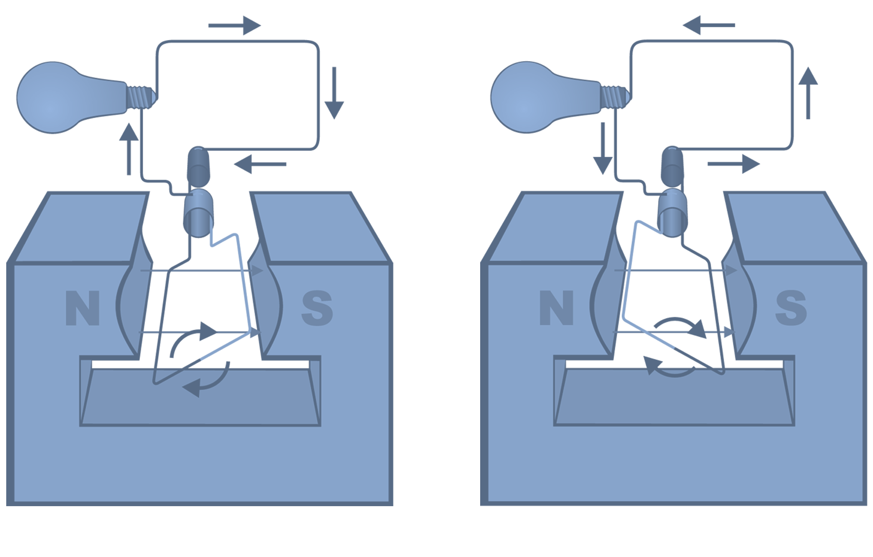
In an alternating current, the current flows first in one direction, then it reverses direction, alternating back and forth in cycles.
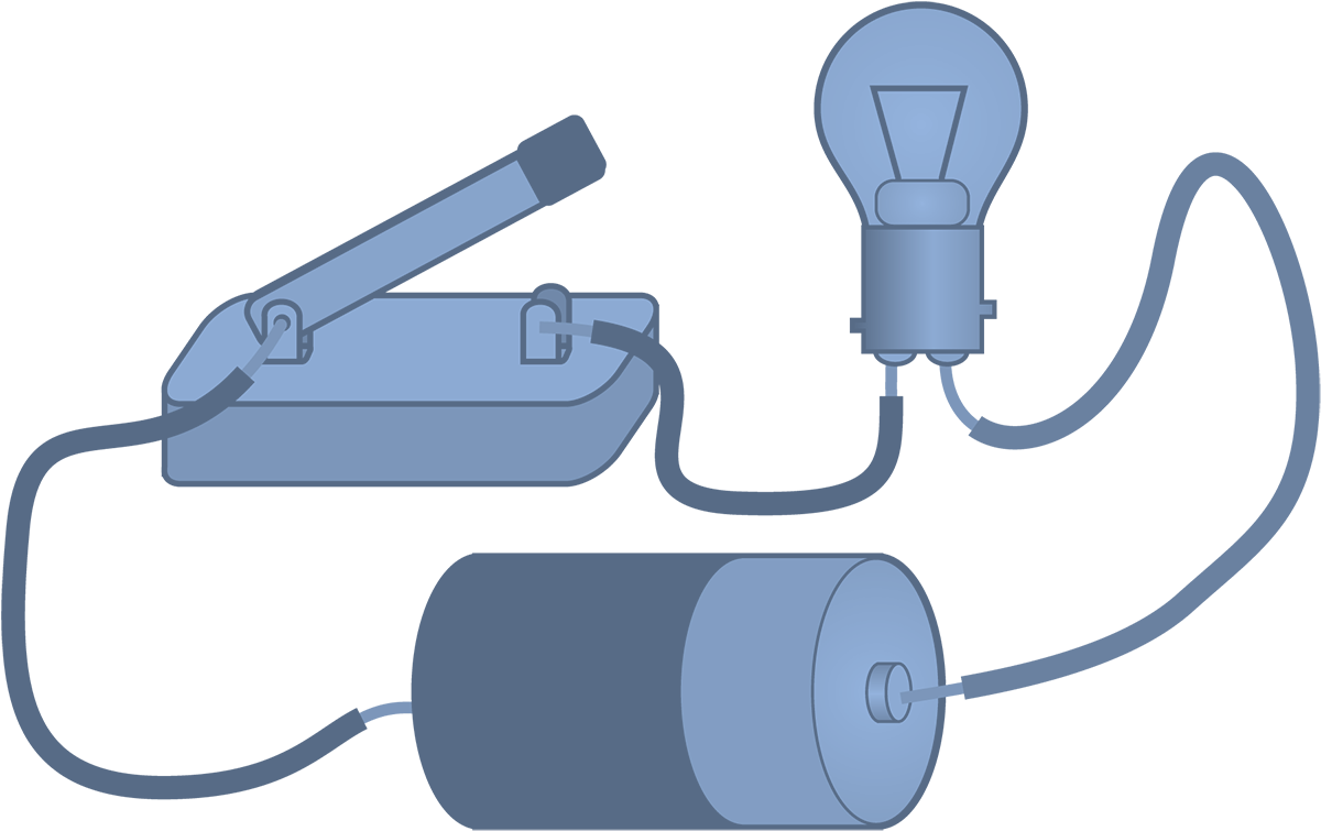
Another reason for DC vehicle systems is that batteries are only able to produce DC current. This works out well because of the relatively low voltage of the vehicle systems, wiring, connectors and switches along with devices can also be lighter. Another aspect of electricity has to do with how the sources of electricity and the device that use the current are arranged and hooked together. In the simplest circuit, the positive terminal of a battery is attached to one terminal of a bulb. The negative battery terminal is attached to the bulb’s remaining terminal. That “complete” circuit allows electrons to flow through the filament of the bulb and allowing the resistance of the filament to create light.
However, if the device in the circuit requires greater voltage, multiple 12-volt, 12 amp batteries can be wired together in a “series circuit” with the negative terminal of one battery connected to the positive terminal of the next battery with the pattern repeated until all of the batteries are linked. If four 12-volt batteries are connected in this fashion, the resulting voltage is 48 volts. The amperage remains the same. The disadvantage with the arrangement is that if one device in a series fails, the whole circuit fails.
A parallel circuit is created if multiple 12-volt, 12 amp batteries are connected with the negative terminal of one battery connected to the negative terminal of the next, until all negative terminals are linked. Likewise, the positive terminal is connected to the positive terminal of the second, using the same pattern until all the batteries are connected. If four 12-volt batteries are connected in this fashion, the resulting voltage is still 12 volts. But this arrangement yields a power output of 48 amps. The advantage of a parallel circuit is that, should one component fail, the circuit doesn’t fail.
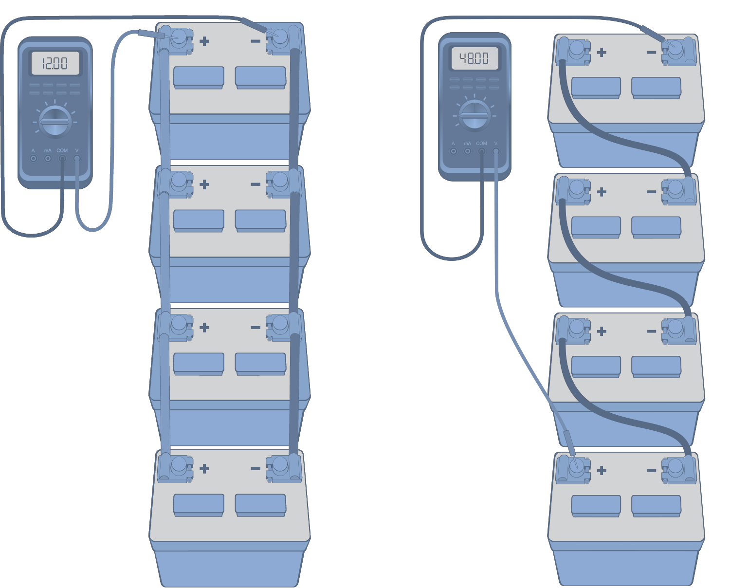
Four 12-volt batteries wired in parallel produce 12 volts.
Four 12-volt batteries wired in series produce 48 volts.
Series and parallel circuits may be combined. For example, a circuit with two batteries connected in series and two in parallel would result in a power output of 24 volts along with 24 amps.
Lights are another application of parallel circuits. For example: driving lights. Two 55-watt headlights in parallel draw 110 watts or 9.2 amps at 12 volts. If one fails, the other will continue to operate, using 55-watts, drawing 4.6 amps, still at 12 volts. In a series circuit, if one failed, the other would go out.
Use the self assessment below to gauge your understanding of this section. Place your answer in the box and then check your answer by clicking on the “show answer” link.
Or, you can skip the assessment.
Instructions:
Read the question.
Place your answer in the box.
Example:
True or False:
You should read the questions and then type your answer into the box.
show answer
True!
Begin:
1. True or False: Atoms all have the same number of electrons.
show answer
False
2. True or False: Amperage is the force that propels electrons through a wire.
show answer
False
3. True or False: Copper is a good conductor because its electrons are tightly bound to its atoms.
show answer
False
4. Which of these is not a basic attribute that describes electricity?
show answer
b) Protons
5. True or False: The movement of electrons from one atom to the next is called electrical current.
show answer
True
6. In a 12-volt system, one amp is roughly the current required to light a:
show answer
c) 12 watt bulb
7. Ohm’s Law shows the relationship between volts (E), current or amps (I) and ohms or resistance (R). For example: E = I x R. If I equals 10 and R equals 5, what is the value of E?
show answer
50
8. Another way to look at the relationship between the three is to discover the amps when the volts are known: I = E÷R. If E = 20 and R = 10, what does I equal?
show answer
2
9. A third way to look at the relationship between the three is to discover the resistance when the volts and amps are known: R = E÷I. If E = 10 and I = 2, what does R equal?
show answer
5
10. If the voltage remains the same and broken wire strands or loose connections raise resistance, what is the effect on current flow?
show answer
b) It drops
11. True or False: Increasing voltage is the best way to get more light from bulbs.
show answer
False
12. True or False: An ohm meter and a continuity tester are both used for testing the resistance in a wire.
show answer
False
13. True or False: The rule of thumb for comparing volts, amps and ohms is that: It takes one volt to push one amp through one ohm of resistance.
show answer
True
14. The length and diameter of a conductor effect its resistance. A short wire of the same diameter and material typically offers:
show answer
b) Less resistance
15. True or False: The higher the temperature of the conductor, generally the lower the resistance drops.
show answer
False
16. True or False: Groups of electrons are constantly seeking a path from areas of high concentration to areas of less electron density.
show answer
True
17. True or False: The "path of least resistance" is always through a newly installed wire.
show answer
False
18. True or False: A short circuit occurs when a bare conductor touches another bare conductor that offers a more direct path to the ground.
show answer
True
19. True or False: An open circuit occurs when there is an interruption or break in the conductor too large for electrons to cross.
show answer
True
20. The term “DC” refers to:
show answer
d) Current always flowing in the same direction
21. Batteries produce …
show answer
a) Direct current
22. True of False: If four 12-volt/12 amp batteries are connected with the negative terminal of one connected to the positive terminal of the next until all are connected, it is referred to as a series circuit.
show answer
True
23. What is the major disadvantage of wiring four 12-volt batteries in series?
show answer
d) If one battery fails the circuit fails
24. A circuit with two 12-volt/12 amp batteries connected in series and two connected in parallel would produce:
show answer
d) 24 volts and 24 amps
25. True or False: A grounded circuit is typically created when a bare conductor is allowed to touch a ground source creating path for the electrons to flow.
show answer
True